The starting point names the loop
Real-to-sim-to-real starts with physical measurements, uses them to revise a simulator or controller, then returns to hardware. Sim-to-real-to-sim starts with a controller developed virtually and returns to the model after physical evaluation. A continuing project can contain both sequences.
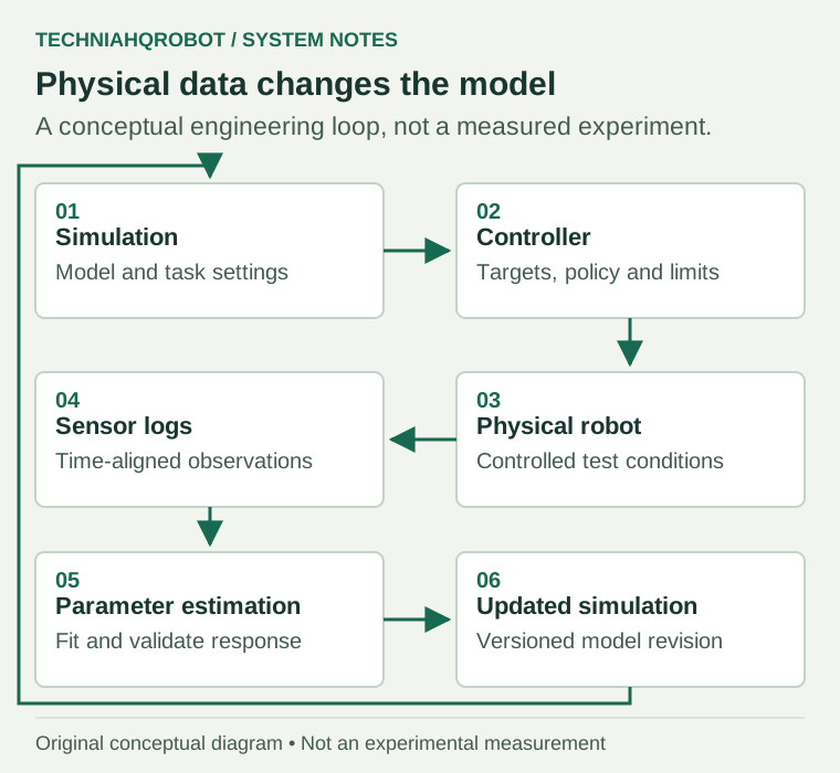
Calibration and control optimization answer different questions. Calibration asks which model response matches recorded behavior. Control optimization asks which actions achieve a task in the model. A controller can compensate for a model error without revealing the underlying physical parameter.
Record the command as well as the response
| Log channel | Why it helps | Interpretation issue |
|---|---|---|
| Joint position and velocity | Compare target tracking, reversal and oscillation | Encoder zero, filtering and time alignment |
| Motor current or reported torque | Study effort limits and load response | Current-derived torque is not a calibrated output-torque measurement |
| IMU acceleration and angular velocity | Compare body rotation and vibration | Mounting frame, gravity convention and bias |
| Foot contact or force estimate | Align touchdown and load transfer | Measured, inferred and simulated contacts differ |
| Camera or motion-capture pose | Observe body or object trajectories | Calibration, occlusion and timestamp uncertainty |
| Control command and reception times | Recover the actual applied target and delay | A sent packet is not proof of its execution time |
Include units, coordinate frames, calibration files, firmware version and the exact controller. Synchronize clocks or estimate their offset before comparing curves. A logging delay can look like a slow actuator; fitting the motor to compensate for the logger would give the wrong correction.
Remote commands introduce another part of this timing chain. Read the teleoperation timing guide
Fit parameters the data can distinguish
Choose a parameter vector before fitting. Candidates include link mass and inertia, effective motor armature, viscous damping, dry friction, target delay, controller gains and contact properties. They are not interchangeable measurements. A single motion may admit several parameter combinations with nearly the same output.
Use bounded excitation suited to the apparatus and its safety constraints. Slow reversals can reveal a different part of the response from fast motion. A leg moving in the air can inform actuator dynamics but cannot identify the friction of its foot against a floor. Changing every parameter at once can hide that lack of information.
Replay recorded commands into the model from a matched initial state. Minimize a stated discrepancy and keep another set of trajectories out of the fit. The held-out set should include motion frequencies or loads that matter to the eventual task. Physically implausible parameter values are a reason to inspect the model and data, not an automatic calibration success.
PACE identifies actuator-related parameters
ETH Zurich’s PACE study calibrated the quadrupeds Tytan, ANYmal and Minimal. The base was fixed and legs moved without ground contact. Commands were replayed in simulation; CMA-ES minimized mean-squared joint-position error across 4,096 parallel environments. [1]
The fitted quantities were per-joint effective armature/inertia, viscous damping, Coulomb friction and joint bias, plus a global delay. Full-robot data were logged at 400 Hz; typical excitation lasted 20–40 seconds. ANYmal and Tytan both fitted a 7.5 ms delay. In-air validation preceded physical locomotion comparisons. [1]
This is a quadruped calibration study, not a humanoid trial. Its in-air procedure does not identify floor friction. Effective fitted inertia may absorb firmware compensation or link-model error; it is not a direct weighing of each link. The authors also caution that fitting PD gains can create nonunique solutions. [1]
ASAP learns a correction for a G1
Carnegie Mellon University and NVIDIA’s ASAP work used G1 trajectories with base pose and velocity, joint positions and velocities, and actions from motion capture and onboard sensing. A learned residual action model changed the simulated response, after which the main policy was fine-tuned. The residual was absent from final hardware deployment. [2]
Physical correction used four ankle degrees of freedom. The authors report 100 collected clips, 30 tracking-policy runs per task and ten minutes of locomotion data; these describe different collection units and must not be added into one trial count. Table V reports physical kick global mean per-joint position error decreasing from 61.2 to 50.2 mm. [2]
This is learned dynamics correction, not evidence that every mass or friction coefficient was identified. The paper reports overheating and damage to two robots during data collection. Its simulator-to-simulator success rates are separate from its physical tracking measurements. [2]
Compare trajectories with declared metrics
| Metric | Definition to record | What can make it misleading |
|---|---|---|
| Joint tracking error | RMSE of joint angle differences, in rad, over aligned samples | Different zero offsets or omitted joints |
| Body orientation error | Relative rotation angle between orientations | Subtracting raw Euler angles across wrap boundaries |
| Contact timing error | Difference between corresponding touchdown events, in s | Different contact thresholds or clocks |
| Position and velocity error | Common-frame displacement and speed differences | Drift or mismatched frame origins |
| Falls per trial | Count under a defined fall criterion and denominator | Removing aborted or assisted runs |
| Task completion | Completed tasks divided by all eligible attempts | Changing the completion rule after observing the results |
Inspect curves as well as averages. A small mean error can conceal a short torque saturation event or a late foot contact that causes the next step to fail. Keep trial duration, speed command, payload and surface in the same record as the metric.
Update, evaluate and return to hardware
- Save the old model and fit result with their hashes so the change can be reversed and compared.
- Test the revised simulator against held-out physical logs before retraining.
- Adjust the controller only after identifying whether the remaining error is in dynamics, observations or the task definition.
- Evaluate the old and new controllers on identical simulated commands and seeds, including conditions outside the fitting set.
- For physical trials, specify supervision, operating limits, intervention rules and a stop response before motion.
- Stop a trial when its declared fault or limit criteria are met; retain that trial in the record.
A fitted model expires as evidence when relevant hardware, firmware or operating conditions change. Replacing a gearbox or changing a control filter can alter the response even when the visible robot and model filename stay the same.
Review the physical risk and conformity distinctions
Use a consistent trial record for the next evaluation. Download the empty trial log template
Sources and verification
- PACE parameter calibration from measured trajectories ↗Bjelonic, Tischhauser and Hutter / ETH Zurich · Read 8 October 2026
September 2025. Quadruped study. In-air calibration does not identify ground friction.
- ASAP physical trajectory collection and dynamics correction ↗He and colleagues / Carnegie Mellon University and NVIDIA · Read 8 October 2026
Sections III and IV, Table V and the limitations section. Version 3, April 2025.
Article history
Added a sourced engineering guide with version-specific references, practical resources and explicit evidence limits.
Report a correction