Walking is a contact problem
Humanoid robots walk by measuring body motion and adjusting joint commands so ground forces support and redirect their mass. Each landing creates a new support point. Balance depends on body velocity as well as posture, so a robot can need another step even while it looks upright. [1]
Mass, pressure and the standing foot
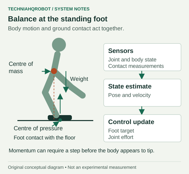
The center of mass is the mass-weighted average position of the robot. Moving an arm or bending a knee moves it. The center of pressure is the location of the resultant normal pressure under the feet. On a flat floor, the support polygon encloses the active ground contacts. Lifting one foot shrinks that region to the remaining foot. [1]
In static balance, with negligible acceleration and no other external contact, the vertical projection of the center of mass must lie inside the support polygon. Dynamic walking also uses momentum. During single support, the body can move beyond a position it could hold motionless, provided the next contact arrives in time. [1]
A compact model makes the difference visible. With flat ground, constant center-of-mass height h and no change in angular momentum, horizontal acceleration follows ẍ = (g/h)(x − p). Here x is the horizontal center-of-mass position, p is the zero moment point and g is gravitational acceleration. The zero moment point is where the net tipping moment vanishes; on this flat contact plane it matches the center of pressure. [2]
If the body is moving forward, slowing it requires backward acceleration. In this model, the pressure point must then lie ahead of the center of mass. A forward step can make that placement possible. The required timing also depends on how fast the body is moving. [1]
One step from measurement to landing
- Measure joint angles, body rotation and available contact signals.
- Estimate body posture and velocity from those measurements. Some learned controllers instead use measurement history without a separate state estimator.
- Choose or adjust the next foothold and the body motion needed to reach it.
- Shift support toward the standing leg. Bend the swinging knee, move the hip and orient the ankle to clear the floor.
- Detect the new foot contact and transfer load across the two feet.
- Compare the resulting motion with the intended motion, then correct the next commands.
A trajectory specifies desired positions over time. Executing it requires forces and feedback. Forward kinematics calculates a foot pose from joint angles and link dimensions. Inverse kinematics finds joint angles for a desired foot pose. Neither calculation alone proves that the motors can supply the required torque or that the foot will keep its grip. [5]
What the hardware measures and moves
| Part | Job during a step |
|---|---|
| IMU | Gyroscopes measure rotation rate. Accelerometers measure specific force. Estimating translation requires accounting for gravity. |
| Joint encoders | Measure rotation at the joints or motors so software can reconstruct limb position. |
| Foot force or contact sensing | Indicates load transfer and touchdown. Some systems estimate contact from other measurements. |
| Hip, knee and ankle actuators | Move the leg and adjust forces through the supporting foot. |
| Motor controller | Tracks the requested joint motion or torque using local feedback. |
Electric motors often use reduction gears to trade motor speed for joint torque. Gears introduce friction and increase the rotor inertia felt at the output. Unitree’s public G1 example sends desired position and velocity, stiffness and damping gains, and feedforward torque. Those fields describe the motor interface, not the complete balance algorithm. [8] [7]
Different ways to choose the next command
Model Predictive Control, or MPC, repeatedly predicts future motion and solves for the next action. Boston Dynamics described historical hydraulic Atlas parkour software that adjusted force, posture and timing around prepared motion templates. That account belongs to the older platform. [3]
Whole-Body Control coordinates tasks while respecting contacts and joint constraints. Support can take priority over an arm trajectory. Herzog and colleagues tested hierarchical inverse dynamics and momentum control on the lower body of a Sarcos humanoid, using 14 leg joints. The physical experiments included balancing on one foot under disturbances. [9]
Reinforcement learning trains a policy by scoring actions across many trials. Berkeley researchers trained a Transformer on randomized simulated environments, then transferred it to hardware without real-world policy training. This sim-to-real process depends on the training conditions covering enough of the real robot’s behavior. Their controller uses a history of observations and actions. It does not need the full sequence of classical blocks described above. [4]
For the current machine’s hardware and operating modes, read the electric Atlas analysis. Its specifications should remain separate from historical hydraulic Atlas results.
To design a learning experiment and retain all evaluation attempts, follow the walking policy training workflow.
How a step fails
Low friction can make the support foot slide. A push changes body velocity. Some disturbances can be corrected while keeping the feet in place. If a recovery step is needed, its landing must be reachable and provide enough traction before the motion becomes unrecoverable. [1] [9]
Stopping a fall, reducing the landing impact and standing up afterward are different tasks. In the RSS 2025 paper Learning Getting-Up Policies for Real-World Humanoid Robots, Xialin He and colleagues trained G1 recovery motions from face-up and face-down positions. Hardware trials included deformable and slippery surfaces. That evidence concerns getting up. It does not establish that the preceding fall caused no damage. [10]
A G1 result with the conditions attached
The 2026 RoM-Nav preprint separates navigation from locomotion. Its Unitree G1 uses Mid-360 LiDAR and a downward-facing ZED Mini. A 5 Hz navigation policy sends velocity requests to a 50 Hz locomotion policy. Those are two software loops, rather than a universal rate for humanoid control. The authors report the work as under review for ICRA 2027. [11]
Separate hardware runs covered a 100 m route and a 10 m climb. In a controlled obstacle experiment, the researchers repeated ten shared start-and-goal conditions with and without a safety filter that adjusts navigation commands. [12]
| Hanging-tube experiment | No filter | Safety filter |
|---|---|---|
| Goal reached | 10/10 | 10/10 |
| Trials with collision | 4/10 | 0/10 |
| Mean time to goal | 5.5 s | 6.9 s |
These trials measure route completion and collisions. They do not measure the largest push the robot can recover from or its fall rate over prolonged use. [11]
The tubes were chosen to give the LiDAR little visible surface. Reaching the goal therefore did not mean completing a collision-free route. In another trial, cardboard covered a glass door and window. The paper also assumes an accurate goal position. These conditions limit what the results establish about unsupervised walking in an unfamiliar building. [12]
Sources and verification
- MIT notes on legged robot dynamics ↗Russ Tedrake, MIT · Read 8 October 2026
Course notes explaining ground reaction forces, center of pressure, support regions and dynamic balance. Definitions are conditional on contact geometry and friction.
- Linear inverted pendulum model ↗Stéphane Caron · Read 8 October 2026
Technical derivation by a robotics researcher. The simplified equation assumes constant center-of-mass height and zero change in angular momentum. The numerical example in the article is an original calculation, not a measured robot result.
- Flipping the Script with Atlas ↗Boston Dynamics · Read 8 October 2026
Historical hydraulic Atlas parkour account describing sensing, offline trajectory design and model-predictive control. It does not document the current electric Atlas controller.
- Learning Humanoid Locomotion with Transformers ↗Ilija Radosavovic and colleagues, UC Berkeley · Read 8 October 2026
Original UC Berkeley project page describing simulation-trained Transformer control, randomized environments and deployment without real-world policy training. It explicitly lists the absence of a separate state estimator in that research system. This account does not identify software used by a fighting robot.
- Numerical inverse kinematics ↗Kevin Lynch and Frank Park, Northwestern University · Read 8 October 2026
Author-provided textbook supplement covering forward and inverse kinematics. Joint geometry alone does not establish dynamic feasibility.
- Proprioceptive External Torque Learning for Floating Base Robot and its Applications to Humanoid Locomotion ↗Daegyu Lim and colleagues, Seoul National University · Read 8 October 2026
September 2023 author manuscript. TOCABI walking experiments compare estimated contact loads against foot force-torque sensors. This source does not evaluate robot fighting or publish an impact detection result for T800.
- Unitree G1 low-level Python example ↗Unitree Robotics · Read 8 October 2026
Manufacturer source code for a 29-motor G1 configuration. The command contains position, velocity, stiffness, damping and feedforward torque fields. It does not disclose a complete walking or fighting policy.
- Actuation, gearing and friction ↗Kevin Lynch and Frank Park, Northwestern University · Read 8 October 2026
Author-provided textbook supplement covering electric motors, encoder measurements, gear ratios, losses and reflected rotor inertia.
- Momentum Control with Hierarchical Inverse Dynamics on a Torque-Controlled Humanoid ↗Alexander Herzog and colleagues · Read 8 October 2026
Author manuscript revised August 2015. The record identifies publication in Autonomous Robots in 2015, DOI 10.1007/s10514-015-9476-6. Physical tests used the lower body of a hydraulic Sarcos humanoid with 14 controlled leg joints and frozen torso joints.
- Learning Getting-Up Policies for Real-World Humanoid Robots ↗Xialin He, Runpei Dong, Zixuan Chen and Saurabh Gupta · Read 8 October 2026
Author manuscript, revised April 2025. The record identifies Robotics Science and Systems 2025. Hardware trials on Unitree G1 cover face-up and face-down starts on several surfaces. Getting up does not establish damage-free falling.
Article history
Clarified recovery without stepping, explained forward foot placement and separated collision-avoidance trials from fall-resistance measurements.
Added a contextual link to the simulation series for the next engineering step.
Report a correction