Eight hours includes the stops
Can a humanoid robot work for eight hours? A shift can contain several battery cycles. None of the three specifications below establishes eight uninterrupted hours on one charge. Manufacturers describe charging or battery exchange for longer operation. Completed work still depends on the task, temperature and time spent recovering from failures. [1] [2] [3]
| Measure | What to count |
|---|---|
| Runtime per battery | Elapsed operation from the stated starting charge to the permitted stopping point, under a defined workload. |
| Active task time | Time actually walking, grasping, carrying or placing objects. Record waiting and recovery separately. |
| Charging downtime | Time unavailable for the job during travel to charging, docking, cooling where required, charging and return. |
| Fleet uptime | Availability across the fleet. State whether the measure is available robot-minutes or coverage of a required number of workstations. |
| Productive hours per shift | A defined output measure. One useful calculation is accepted task cycles multiplied by a reference cycle time. State the definition beside the number. |
A powered robot waiting for a conveyor has runtime but no completed cycle. A second robot may cover a station while the first charges. These arrangements change the work delivered during the shift even when each machine has the same battery endurance.
G1, Atlas and Digit 5 specifications
Specifications checked on 8 October 2026. These are manufacturer records with different workloads and hardware stages. They are not an independent endurance ranking.
| Robot | Battery runtime | Charging or swapping | Conditions | Official record |
|---|---|---|---|---|
| Unitree G1 base, 23 DoF | About 2 hours | Removable pack; about 1.5 hours charging | Runtime workload and payload are unstated. Manual pack handling. | G1 product table and Battery and Charger User Manual v1.0 |
| Boston Dynamics Atlas product version | 4 hours typical use; 2 hours heavy lifting | Autonomous exchange about 3 minutes; pack charging 1.5 hours | No detailed lift frequency or load schedule accompanies the runtime figures. | Atlas specification sheet and product operating note |
| Agility Robotics Digit 5 | 90 minutes | 9 minutes autonomous charging; 10 to 1 run-to-charge ratio | Preliminary internal estimates on pre-production hardware and software. | 15 September 2026 announcement and Digit 5 product page |
Agility also advertises more than 20 productive hours per 24-hour day. Its launch announcement schedules Digit 5 early access for the first half of 2027 and general availability by the end of 2027. The company's existing Digit 4 customer operating records do not measure Digit 5 battery performance. [3]
The G1 charging figure comes from the 2024 manual. Its charger output differs from the product table. Confirm the supplied pack and charger revision. Atlas figures come from the sheet marked 23 December 2025; the accompanying product note identifies typical use. [4] [2] [5]
Where the electricity goes
Actuators
Joint motors convert electrical input into shaft motion. Mechanical power equals torque multiplied by angular speed. Electrical demand also includes winding resistance, bearings, gearing and drive losses. A peak joint torque rating alone cannot predict average battery consumption. [7]
Locomotion
Walking moves the body mass and swings the legs. Each step includes acceleration, deceleration and contact with the floor. Turning changes the motion of the body and feet. Climbing raises the centre of mass against gravity. A push can require extra steps and corrective joint torques. The route, speed and control policy therefore belong in an endurance test.
Posture also matters. Bent knees can require sustained joint torque even while the feet stay in place. Energy recovered during braking depends on the motor drive and battery system; assume no recovery credit without measurements.
Read how humanoid walking controllers manage contact and balance.
Manipulation
Lifting a box adds mechanical work. Holding it away from the torso increases the torque required at the shoulder. An electrically held gripper or joint can draw current while motionless. Mechanical brakes, springs and transmission design can change the holding demand. [7]
Computing
Control loops, perception and AI inference keep processors active. Hardware, model size and processing rate affect demand. The G1 product table lists an eight-core CPU; EDU configurations may add a computing module. Record the installed configuration when measuring runtime. [1]
Sensors
Cameras and LiDAR need electrical power while collecting data. IMUs report body motion and joint encoders report joint position. The G1 lists a depth camera and 3D LiDAR. Their individual power draw is not supplied in its product table. [1]
Cooling
Heat passes through motor housings and surrounding structures into the air. Fans or liquid pumps consume power where fitted. G1 specifies local air cooling. A cooling label alone does not establish a sustained workload at a given ambient temperature. [1] [8]
Calculate runtime from usable energy
| Unit | Meaning |
|---|---|
| Watt, W | Power, the rate of energy use. One watt is one joule per second. |
| Watt-hour, Wh | Energy used by a one-watt load over one hour. |
| Kilowatt-hour, kWh | 1,000 Wh. |
| Ampere-hour, Ah | Electric charge. Multiply by an appropriate nominal voltage to estimate rated energy. |
| Volt, V | Electrical potential difference. Battery nominal voltage and maximum charging voltage are different values. |
Runtime (hours) = Usable battery energy (Wh) / Average electrical power (W)

1,000 Wh / 500 W = 2 hours
1,000 Wh / 750 W = 1.333 hours, or 80 minutes
Use energy available between the chosen start and stop limits, and average power measured at the same battery boundary. The 500 W figure must represent the whole intended job. Using a peak motor rating or a processor's power setting would leave other loads uncounted.
The G1 manual states 46.8 V nominal, 9,000 mAh, or 9 Ah, and 421.2 Wh. The arithmetic is 46.8 × 9 = 421.2. This is rated pack energy. It does not establish usable energy after discharge limits, temperature effects and ageing. Multiplying 9 Ah by charger output voltage would use the wrong voltage basis. [4]
Workload changes alter average draw. Temperature, discharge limits and electrical losses alter the energy that can reach the loads. Energy capacity also adds mass and occupies space. The March 2026 Energy Use perspective discusses these pack-level trade-offs and power-system architecture; it provides context rather than a new endurance experiment. [9]
Heat can limit the next lift
Current encounters resistance in a motor winding. Resistive heating follows P = I²R. Doubling current produces four times the resistive loss at unchanged resistance. A joint holding a box may have zero shaft speed while current continues to heat the winding. Friction in bearings and gears adds losses during movement. [7]
Picture repeated box lifts from a waist-height conveyor to a chest-height shelf. The first cycle starts with cooler hardware. Continued lifting can leave less time to reject heat before the next cycle. Winding temperature and the surrounding air affect the sustainable operating range. Peak torque is available only within the hardware's electrical and thermal limits. [8]
Thermal derating means reducing permitted output as temperature rises. ODrive documents a controller example that lowers its current limit between two temperature thresholds and stops closed-loop operation after further overheating. This is a documented controller behaviour, without implying that G1, Atlas or Digit uses ODrive. [10]
What the G1 arm experiment measured
A June 2026 preprint by Deniz and colleagues studied a physical G1 configuration with seven left-arm joints and a Dex3-1 hand. The robot stood with a safety tether and crane; the right arm rested. The authors fitted a power model to 897 filtered trajectories and tested it on 46 additional trajectories. Electrical readings arrived at about 1 Hz. [11]
Validation produced a root-mean-square prediction error of 3.58 W. The fitted model attributed 42.4% of predicted power to copper losses and 38.2% to viscous friction on that validation set. Those are model terms inferred from electrical measurements. They are not measured heat fractions for the whole robot. [11]
Charging and battery exchange
Manual replacement and powered swapping
A removable battery can be changed by a person. The G1 manual requires the battery to be off and removed for charging, and cooled to room temperature after operation. Cooling adds waiting time beyond the quoted charge duration. [4]
Hot swapping means the electrical system stays powered during replacement through a supported supply arrangement. A removable pack or an autonomous exchange does not, by itself, document that capability. Check the manufacturer's permitted procedure, retained state and restart requirements before assigning an exchange time.
Autonomous exchange and charging docks
Atlas is described as navigating to a station and replacing its own battery. Its approximately three-minute exchange leaves pack recharging to the charging system. A usable charged pack must be ready for the next visit. The published exchange time does not quantify customer availability over a complete shift. [2]
Digit 5 instead advertises autonomous dock charging. A 90-minute run followed by a nine-minute charge gives 90 / (90 + 9), or 90.9%, availability in a repeated ideal cycle. This calculation excludes travel, waiting, failed docking and other stops; it is not a measured task success rate. [3]
Contacts, retention and scheduling
Charging connections need correct seating and controlled power transfer. Boston Dynamics documents an interlock that closes before Spot Dock supplies power and disconnects as Spot rises. Spot is a quadruped. This example does not establish the construction of an Atlas battery station. [12]
For a battery exchange, ask how the system confirms the pack is retained and electrically connected before work resumes. The public Atlas sheet does not disclose its latch detection or contact sequence. The acceptance record should include failed insertion, incomplete locking and recovery procedures.
A fleet schedule also has to reserve chargers, spare packs and the route to the station. Two machines with equal runtime can lose different amounts of work when one has a nearby available dock and the other queues behind another robot. Include charger faults and staff response time in the availability log.
An eight-hour shift worked through
Assume an eight-hour shift, 1,000 Wh usable energy per full pack and a constant average battery draw of 500 W throughout powered periods. That gives 120 powered minutes per pack. Start with a full battery. Strategy A stops for 30 minutes to recharge. Strategy B exchanges a pack in three minutes, with a charged spare always ready. Both service intervals include all travel and handling in this simplified example.
| Strategy | Powered intervals in minutes | Battery service | Powered availability |
|---|---|---|---|
| A. Recharge the same pack | 120 + 120 + 120 + 30 = 390 | 3 × 30 = 90 minutes | 390 / 480 = 81.25%, or 6 hours 30 minutes |
| B. Exchange for a charged pack | 120 + 120 + 120 + 111 = 471 | 3 × 3 = 9 minutes | 471 / 480 = 98.125%, or 7 hours 51 minutes |
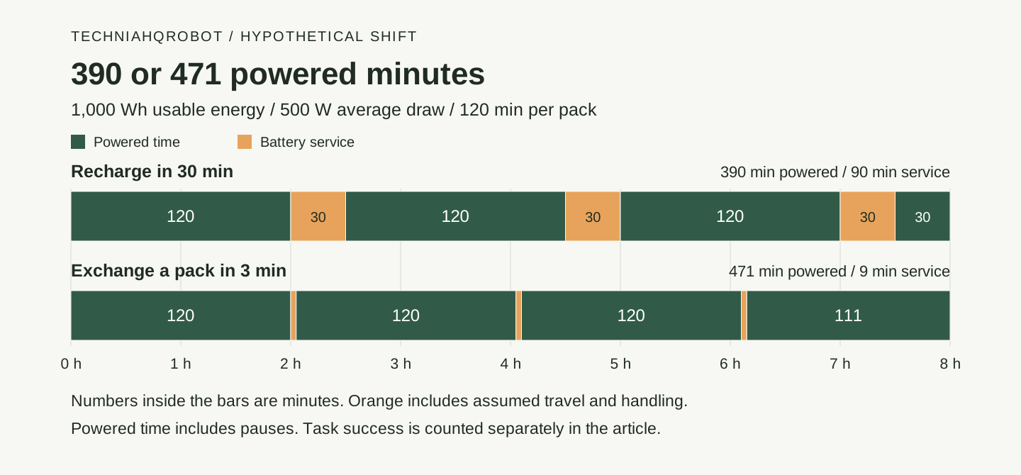
The final powered interval ends at minute 480. Neither schedule includes a recharge after the shift. Strategy A uses 500 × 6.5 = 3,250 Wh at the battery boundary during powered operation. Strategy B uses 500 × 7.85 = 3,925 Wh. Charger input energy would also include charging losses, which are unspecified.
Strategy B assumes at least two compatible packs. With a 30-minute off-robot recharge, the depleted pack would finish before the next 120-minute powered interval ends, provided cooling and handling fit the stated service plan. Extra travel, a warm pack or a failed lock check reduces the availability shown.
Count accepted work after powered time
Now take Strategy A's 390 powered minutes. Reserve ten minutes for maintenance and twenty for recovery and operator intervention. These pauses stay inside the assumed 500 W powered budget. That leaves 360 minutes for attempts. Assume every attempt, including a failed attempt, takes 60 seconds.
Attempt time = 390 - 10 - 20 = 360 minutes
Attempts = 360 / 1 = 360
Assumed success rate = 95%
Expected accepted cycles = 360 × 0.95 = 342
Good-cycle-equivalent time = 342 × 1 minute = 5 hours 42 minutes
Expected accepted throughput = 342 / 8 = 42.75 cycles per shift-hour
The 95% rate is an assumption, and 342 is an expected count. The twenty recovery minutes are additional to failed-attempt time. Report actual intervention counts and completed cycles in a site trial. A slower cycle, extra cooling pause or lower success rate changes the output even with unchanged battery runtime.
Download the interval-by-interval schedule as CSV.
Download the calculation script for Node.js. It prints the assumptions, intervals and results without external packages.
Questions for a task acceptance trial
Use the same box, route, lifting height, pace and stopping rule across repeated trials. Record ambient temperature, starting charge, pack revision, software, installed computers and payload. Ask for the full run log alongside the quoted duration.
- What average and peak battery power were measured during this exact task? Which electrical boundary did the meter use?
- What starting charge, discharge cutoff, payload and motion cycle produced the advertised runtime?
- How much time was spent cooling, travelling, docking, charging and returning to the work area?
- How long did a complete battery exchange take, including lock checks, restart and failed attempts?
- Which task has been evaluated at a customer site on this exact hardware generation? What were the sample size and trial duration?
- How many attempts produced accepted work, and how many required a person to intervene?
- What temperatures and current limits were reached after repeated lifts? Did cycle time or available torque change?
- How many compatible spare packs and chargers are required for the proposed shift schedule?
Read the guide to humanoid machine safety and task risk assessment.
Sources and verification
- G1 version and specification table ↗Unitree Robotics · Read 8 October 2026
Base and EDU columns differ. Runtime lacks a stated workload.
- Atlas product specification sheet ↗Boston Dynamics · Read 8 October 2026
Two-page PDF carrying the revision date 23 December 2025. The specification table on page two was visually checked.
- Digit 5 launch specifications and availability ↗Agility Robotics · Read 8 October 2026
15 September 2026 manufacturer announcement. Digit 5 forecasts are separate from the reported Digit 4 field records.
- G1 Battery and Charger User Manual v1.0 ↗Unitree Robotics · Read 8 October 2026
2024 manual. Specification and charging pages were read as original page images. Its charger output differs from the current product table.
- Atlas safety, service and factory integration ↗Boston Dynamics · Read 8 October 2026
Manufacturer account of proximity stopping, padding, battery replacement and supervision through Orbit.
- Digit 5 product specifications and qualification ↗Agility Robotics · Read 8 October 2026
The page labels specifications preliminary estimates from internal testing and benchmarking of pre-production configurations.
- DC and EC motor equations and thermal behaviour ↗maxon · Read 8 October 2026
November 2014 motor reference. Printed pages 42 and 46 explain power, winding losses and thermal behaviour. These are motor principles, not G1 measurements.
- Continuous operation range of BLDC motors ↗maxon · Read 8 October 2026
Updated 29 August 2024. Continuous output depends on winding temperature and heat dissipation; example temperature limits belong to the documented motor.
- A perspective on humanoid battery technology ↗Deng, Chen and Mo, Energy Use · Read 8 October 2026
Published 25 March 2026. Perspective on battery and power-system design; no new whole-body endurance experiment.
- Motor-controller temperature regulation ↗ODrive Robotics · Read 8 October 2026
Documentation 0.6.12 describes independent inverter and motor thermal zones, current reduction and stopping. No claim that the compared humanoids use this controller.
- Identification of a Physics-Based Electrical Power Consumption Model for the Unitree G1 Humanoid Arm ↗Deniz and colleagues, arXiv · Read 8 October 2026
14 June 2026 preprint. Physical seven-joint left-arm experiment; whole-body battery endurance and temperature rise were not tested.
- Spot Dock charging interlock ↗Boston Dynamics · Read 8 October 2026
Official indexed support text describes the contact interlock. Direct page rendering was incomplete. Spot is a quadruped; its mechanism is not attributed to Atlas.
Article history
Separated stated battery capacity, advertised runtime and the missing test workload into distinct table columns.
Expanded the energy guide with manufacturer battery records, actuator heat, a scoped G1 arm study and reproducible shift calculations. The existing guide URL is retained.
Report a correction